Arduplayer, Arduino Based Music Player
This page documents the realization of an Arduino music player based on the original idea and code provided by Kalum in his blog. The player will play Ogg Vorbis/MP3/AAC/WMA/MIDI + FLAC (!!!) and on Arduino DUE even WAV audio files.It can be directly connected to the line input of an amplifier or to a pair of fine earphones. The quality of the internal DAC is excellent.
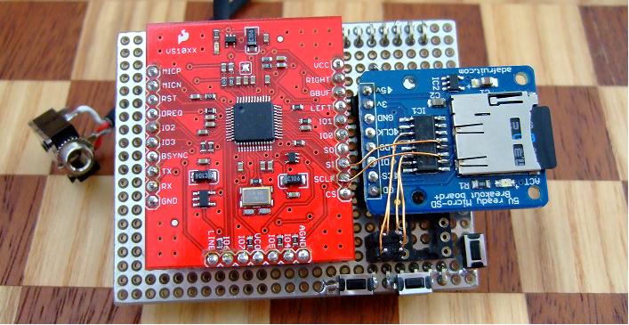
With the
VS1053b breakout from Sparkfun, the
SD breakout from Adafruit, some headers and a piece of prototyping board, a simple shield can be made.
These breakouts are the only ones I have had experience with, but similar choices should work as well.
This SD adapter has two unused level shifters that -with some fiddling- can be put to good use,
more on that later. The VS1053b breakout has a superb board layout and includes the basic ESD protection at
the audio output as proposed in the VLSI recomendation for the VS1053.
The VS1053 and the SD card interface to Arduino via the SPI. To keep the shield physically compatible to different Arduino board types, the ICSP header is in this case the interface of choice. See details at the Arduino SPI library. A further advantage of this approach is that the shield header for the digital pins 8 throgh 13 can be spared thus avoiding the cumbersome adaption of the shield connector to the Arduino non standard pitch between the two digital pin headers.
To diferentiate which device is being addressed (VS1053 or SD card) chip select signals are used [BSYNC, CS for VS1053 and CS for the SD card]. Note the VS1053 requires two chip select signals itself to diferentiate between audio [BSYNC] or control [CS] data.
The shield can safely be used also with the Arduino DUE. All signals interfacing from the shield towards the Arduino remain in the 3.3V level domain. Depicted below is the schematic attempting to reflect also the position of most of the components and headers on the shield.
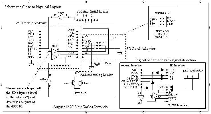
From Arduino towards the VS1053 the clock, the data, the BSYNC and the CS signals need level shifting down to
3.3V. The Arduino DUE already delivers 3.3V signals that do not require level shifting, but to keep the shield compatible
to both Arduinos (UNO & DUE) 'level shifting' is done in both cases. This does not impair operation in neither case and we
are always on the safe side.
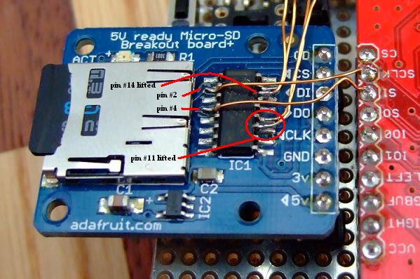
The clock and data lines are already dealt with on the SD breakout card and can simply be tapped off pins 2 [clock] and 4 [data] at the 4050 level shifter IC and connected to the corresponding VS1053 breakout pins [SCLK and SI].
For the VS1053 audio [BSYNC] or control data [CS] selection signals we need two additional level shifters. Luckily we can take advantage of two unused level shifters available on the 4050 IC on the SD card adapter. To get access to these a little tricky operation is required; The corresponding level shifter input Pins 11 and 14 need to be lifted off the PCB pads. These pins are originally grounded to avoid noise when the level shifter is not used.
A steady hand, good comand of the soldering iron, a good clamp to hold the board in place and a pair of very thin and pointy pair of tweezers or other pointed object you consider suitable are required for this operation. The outputs 12 [BSYNC@3.3V] and 15 [CS@3.3V] can be soldered directly on the pins without having to lift them off the PCB.
The wires for these two level shifters go to a 4 pin header on the main board of the shield (see top picture) and from
there to the corrsponding pins.
This way I only need to desolder the SCLK and SI wires and can remove the SD card adapter from the shield if need be,
by simply plugging it out.
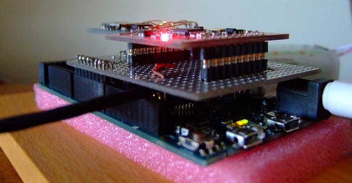
Both breakout boards are plugged into the main shield board like integrated circuits on their sockets. Below is a side
view showing this for the VS1053 breakout:
At the bottom of this page you find two sketeches, one for the Arduino UNO and compatibles (I run it on a Duemilanove)
and a second one for the DUE. Basically the code is the same as Kalum's original. I only added 'minor' changes:
- Some CS pins were changed to better suit the way I chose to interface the shield.
- For the DUE the 'fastDigitalWrite' instructions are not necessary and not supported so they were changed to 'digitalWrite'.
- Originally the plugin code that is necessary to add FLAC playback functionality to the VS1053 was stored in programm memory at the expense of reducing the available programm memory for further sketch extensions. So to free memory the FLAC pluging code was moved out to the SD card as a file named PLAYFLAC.BIN. The code was modified to check for the presence of this file on the SD root's directory and if found it is loaded to the VS1053 during initialisation.
- In the sketch for the Arduino DUE, the default SPI clock divider is set to 10 (#define SPI_DEFAULT_SPEED 10) yielding 8.4 MHz SPI clock. At that time I was not clear about how far I could go with this, later I found that even doubling the SPI speed to 16.8 MHz (#define SPI_DEFAULT_SPEED 5 which) was no problem. With this SPI speed the DUE can happily play PCM 16 bit stereo WAV audio files sampled at 44.1KHz. Give it a try and modify this setting to check it out.
To get FLAC decoding going just copy the plugin file (PLAYFLAC.BIN at the bottom of this page) to the SD card's root directory.
If the plugin is not present the loading is skipped and FLAC coded files will not be played back. All other supported formats still
work. Note that each time the Arduino resets, the VS1053 is reset too and the FLAC plugin code is re-loaded to the VS1053.
While the FLAC plugin is loaded to the VS1053 the red LED on the Adafruit SD card adapter blinks but no sound is produced. Detection and loading of the FLAC pluggin is also notified on the Serial Monitor. The presence of non decodable files on the SD card does not upset the VS1053, they are send by Arduino to the VS1053 but it seems to ignore their data and no audio is generated.
As soon as the Arduino has finished initializing it will start playing the first audio file it encounters on the SD card´s root directory regardless of its format (MP3, FLAC, Ogg Vorbis, ...). This means audio files with different formats can be mixed. With the Next/Prev. buttons it is possible to move to the next or previous file. Via the IDE terminal also a bass boost (b) and a "spatial" audio mode (s/x) can be enabled/disabled. Functions like trebble and bass control or changing the volume can easily be added. A look at the code and at the VS1053 data sheet should clarify how this can be acomplished.
Finally I'd like to add that I am not an experienced programmer, all I know comes from experimentig with Arduino and Kalum's sketch remains a mystery to me in many aspects still.
!!! Important Note !!!:
The audio interface on the VS1053 has a buffered ground which is DC level shifted to 1.25V to null out the same DC component present on the left and right output pins of the audio output. This means that this buffered ground has a DC offset with respect to power supply ground of the VS1053 and consequently also to the Arduino ground!
If this shield is used in combination with other components like an amplifier or a PC you must make sure that their grounds are not connected together, this would be the case if e.g. the PC or amplifier and the Arduino share a common power supply (i.e. USB connection).
Not observing this might short the DC present on the buffered ground and most likely damage the VS1053 chip. Please check the document named Connecting Analog Outputs at VLSI Solution VS10xx Application Notes page for details and how to overcome this.
As long as the Arduino is powered from batteries (as I run it) and the ground of Arduino power supply is not connected anywhere else there is no danger. Also powering the Arduplayer via USB from a PC while only using headphones connected to it is save too.
Arduplayer Code & Plugin
Aug. 10. 2013, Carlos Durandal
(last update October 27 2013)
(last update October 27 2013)