The 6P7S-i SE Amplifier
The 6P7S beam tetrode driven with either a single triode, an SRPP or -as presented here- with an Aikido circuit, has revealed itself as a superb performer. Most satisfactorily in triode or ultralinear mode when no global feedback is used.
The Sound
Full of energy the amp surprises with a tight and strong bass and a beautiful and delicate sound. Everything sounds right and it really makes you feel the music under the skin. It makes you swing, tap and dance! Amazing what 3 watts can do. Sure the Aikido driver and the OPT from Reinhöfer have their share but I guess the combination is the key for the successful alchemy.A breathtaking experience was to listen to Rismky-Korsakov's masterpiece from this gem of a record 'Scheherazade - Capriccio espagnol. Orchestre Symphonique de Montreal / Charles Dutoit' issued by DECCA (410253-2). Like witnessing a most spectacular firework display. Full of explosive virtuosity contrasted with delicate and complex light patterns (Track 4). A wealth of colors and emotion. Lots of room wide and deep for all the instruments of the orchestra to fit and perform clearly on their own as in open space.
Schematics

The schematics try to reflect the wiring approach I took. Each stage including the power supply has its own ground bus or ground star point. Output stage and input driver grounds are -per channel- individually taken to the power supply ground point. The power supply ground should be after and NOT at C2. Wiring as depicted in the schematic should assure this.
Also the input ground of the RCA connectors are individually directly tied to the power supply ground. The shield of the input cable leading to the volume control is connected only at the RCA side.
Originally I aimed for 250V and 60mA plate values. In preparation the LM317 were mounted on heatsinks and instead of taking the whole primary winding of the OPT I would use the 50% tap to avoid saturation. In the end the plate current used is 50mA and the voltage between plate and cathode is 244V due power supply limitations but I kept the 50% tap connection on the OPT.
The power transformer was originally meant for a different project. It fits alright here, yet to have some more headroom a HT secondary with 230V and 180mA instead of the 225V and 150mA would be preferable. Other windings: 2x 6,3V 2A, 5V 2A.
The OPT has intermediate taps at 25% and 50% allowing for ultralinear operation if desired and leaving room for experiment.
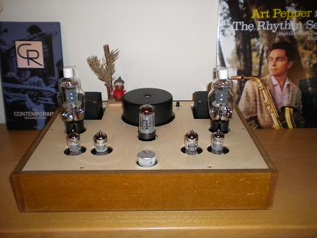
Construction Pictures